WITH EXHAUST OF NON-CONDENSABLE GAS
Hiroyuki Takazawa, Sam Tukana*, Masatsugu Amano, Tadayoshi Tanaka
Electrotechnical Laboratory, MITI Tsukuba, Japan
*The University of The South Pacific
Suva, Fiji
Abstract
In Open-cycle Ocean Thermal Energy Conversion (OC-OTEC) system, the net output power is the difference between the gross power output and the internal power consumption of the system. The main internal power consuming devices of the OC-OTEC system are the intake pumps for the cold deep sea water and the warm surface sea water, and the vacuum pumps or compressor for exhausting non condensable gases from the system. Therefore, the reduction of the internal pumping power of the system is important for the increase of the net power output of the system.
When surface sea water is flash evaporated in the evaporator, dissolved non-condensable gas are released. The non condensable gases have to be continuously removed, otherwise considerable reduction system power output would result. Exhaust vacuum pumps or compressors are used to remove or exhaust this non-condensable gases from the condenser chamber. To determine the pumping power required to remove the non condensable gases, a clear relationship between condenser performance and non-condensable gas concentration have to be established. This paper outlines the experiments performed to obtained this relationship for the particular condenser configuration specified within. The experimental results show that when the concentration of non condensable gases in the condenser exceed 5% by volume, the performance of condenser measured by it's thermal effectiveness ec drops to below 0.8. To keep the non condensable gas concentration below 5%, the exhaust gas discharge rate from the condenser should be at least 10 times the rate at which non condensable gases are released in the evaporator.
Introduction
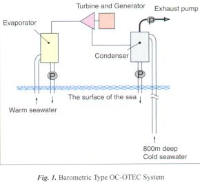
A typical barometric type OC-OTEC system is shown in Figure1. In open cycle system warm sea water from the surface of the ocean is flash evaporated in evaporator to produce steam. The surface sea water normally contain dissolved gases which are released during the flash evaporation process. The generated steam is then used to drive a turbine coupled to a electrical generator. The steam is then condensed using cold sea water drawn from ocean depth. The released dissolved gases (also called non condensable gases) have to be continuously removed form the condenser using an exhaust pump.
Increasing efficiency is important in the production of electric power from low energy density natural resources such as ocean thermal energy. One way of increasing the energy efficiency of the OC-OTEC system is to reduce it's internal power consumption.
 One of the important component of the internal power consumption in an Open-cycle OTEC is the exhaust pump required to evacuate non-condensable gases accumulating in the condenser. In case of the pilot OC-OTEC test plant presently operating in Hawaii1), the actual compressor power required to exhaust the non condensable gases is around 40 kW out of the total gross output power of 210kW. It accounts for about 30% of total internal power consumption.Non-condensable gas in OC-OTEC system, comes from the dissolved gases in sea water when it is vaporized under vacuum condition in the evaporator. Accumulation of non-condensable gases in the evaporator will result decreased condenser performance and in turn reduces the turbine power output. The amount of non condensable in the system will depend on the amount of dissolved gases in the sea water and it is therefore important to determine dissolved gas concentration in sea water for any site where an OC-OTEC system is to be established.The evacuation of non-condensable gases from the system involves the exhausting of steam from the top of the condenser vessel. This exhaust flow rate will determine the final concentration of the non condensable gases in the condenser which in turn determines the performance of the condenser. Condenser performance will be significantly drop when the concentration of non condensable gases reach a certain critical level. It is therefore essential the quantitative relationship between non condensable gas concentration and condenser performance be established. The minimum exhaust gas flow rate from the condenser to maintain the required maximum non condensable gas concentration can then be determined. Exhaust gas pumping power can then be estimated. The objective of the experiment described was to determine the relationship between non condensable gas concentration and thermal performance of the particular condenser configuration specified below.
Experimental Equipment
Figure 2 shows the experimental setup used. The main components of the experimental equipment are evaporator, condenser, warm and cold water pumps, vacuum pump and the water storage tanks. As shown in this figure, a turbine-generator is not installed. An expansion valve is used as the substitute of a turbine.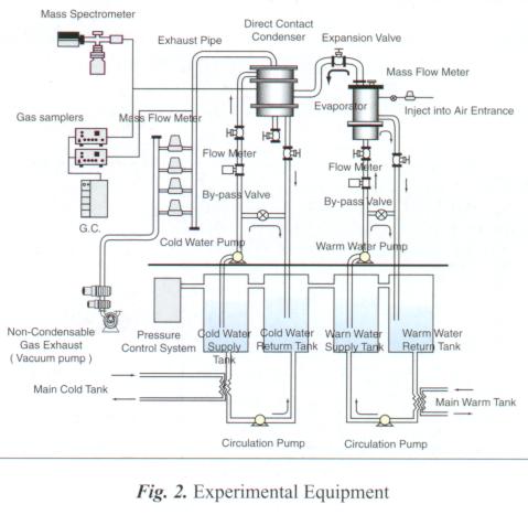 Table 1 gives the specifications of the main components mentioned above. The experimental setup is operated in closed cycle using fresh water. Since the experiments are carried out under vacuum condition, any dissolved gas in the water would have to come out of solution and thus the circulating water contains no dissolved gas. Therefore in order to simulate the effect of non-condensable gases in the condenser, air has to injected into the evaporator at different flow rates. The air injection flow rate was variable between 0 and 0.5 liters/min. The exhaust gas flow rate was measured with four mass flow meter as shown in Figure 2.
Figure 3 shows the configuration of the spout type evaporator with five nozzles (inside diameter is 30 mm). A mesh was placed around the nozzle to create finer size water droplets after spouting.
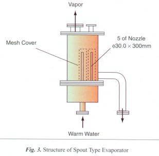
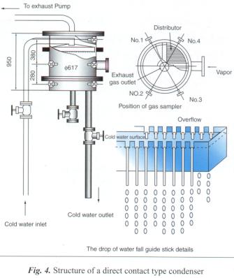
Figure 4 shows the details of the direct contact type condenser and the cold water distributor placed at the top of condenser. The distributor convert the cold stream of water into fine line droplets and evenly distribute them over entire cross section of the condenser. The distributor is made of 16mm wide channel sections spaced at a distance of 20 mm apart. On the sides of these channel sections, 5 mm wide windows are cut on which guide rods are placed as shown. As these channels fill up the cold water overflow onto guide sticks creating fine uniform droplets.
Non condensable gas concentration was measured at 12 different points inside the condenser. Gas samples from these points were analyzed using a Mass Spectrometer and cross checked by Gas Chromatography analysis. Non--condensable gas concentration in exhaust-gas was also measured.
Experimental Results and Discussion
The measurement of the performance characteristic of condenser require varying the air injection flow rate into the evaporator and the exhaust gas flow rate from the condenser. Air injection flow rate was varied by means of a needle valve and measured with mass flowmeter. The flow rate of exhaust gas was measured with four mass flowmeter in parallel. The warm water flow rate and temperature to the evaporator were held constant at 5.0 m3/hr and 30¢J. The cold water flow rate and temperature to the condenser were also held constant at 4.5 m3/hr and 6¢J. The outlet water temperatures and steam temperatures and pressures in both the evaporator and the condenser were also measured. Thermal effectiveness were then calculated.
Figure 5 shows the results obtained. The vertical axis represents the thermal effectiveness of the condenser ec. The horizontal axis represents ratio of exhaust gas flow rate and air injection flow rate. Condenser A is the new condenser as shown in Figure 4 and condenser B is the modified original spout type2) with packed column using plastic Tellerette rings (external diameter: 47 mm, height: 19 mm, coil:3x3 mm, number: 9 rings, surface area: 185 m2/m3, void ratio: 88%).
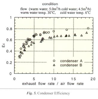
The result show that condenser A performing better than condenser B for all air and exhaust gas flow conditions. For example, the thermal effectiveness that condenser B attains at flow rate ratio of approximately 10 is also attained by condenser at about half the flow rate ratio. This result means that using condenser A in OC-OTEC system would require less exhaust pumping power than using condenser B. The high performance of condenser A is due to more uniform distribution of cold water droplets across the entire cross section of the vessel. For condenser A, the thermal effectiveness falls sharply below flow ratio of 5 and remains fairly constant above flow ratio of 10. In other words, the effect of non condensable gases on the thermal effectiveness of the condenser can neglected at flow ratios above 10.
Figure 6 is the results that measured the concentration of the air which was non-condensable gas in condenser when sampling probe was put in the place shown by Figure 4. According to the figure, non-condensable gas was distributed in condenser non-uniformly, and the middle of the stairs measurement part which there was steam inlet showed the highest concentration.
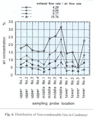
The concentration was a little high the upper section when compared the upper section and the lower section. A place of No.4 that was the right side of steam inlet was high concentration most, and this trend was similar in the lower section. In Figure 6, steam including non-condensable gas diffused in the whole shifting the right side a little from steam inlet.
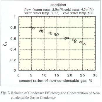
Figure 7 shows the relation between condenser performance and average non-condensable gas concentration. As expected, the result show that condenser performance increase as the non condensable gas concentration decrease. The non-condensable gas concentration needs to be less than 5 % to keep the thermal effectiveness above 0.8.
The non-condensable gas concentration in exhaust pipe arrangement was measured with Gas Chromatography. This measured value was found to be equal with average value of concentration of non condensable gas in the condenser chamber as measured by the mass spectrometer. As further confirmation to the measured gas concentration values, mass balance calculation were also carried out using the measured flow rates. A plot of calculated values of non condensable gas flow rate in exhaust stream against the measured air injected flow rate is shown in Figure 8. The curve shows good agreement.
Conclusion
In comparison of 2 types condenser, new direct contact type condenser produced experimentally was high efficiency, because exhaust flow rate was about 1/2 to obtain performance of same. On the other hand, performance of condenser was influenced the concentration of non-condensable gas greatly. It became clear that exhaust flow rate of around 10 times of quantity of dissolved gas released was necessary to get high performance ec=0.8. The non-condensing gas concentration was less than 5%.
It was installed sampling probe to condenser, and the non-condensing gas concentration distribution was measured. According to the measurement, steam including non-condensable gas diffused in the whole shifting the right side a little from steam inlet. We were able to make clear relation of performance of condenser and non-condensing gas concentration in thing of equipment. Relation of exhaust flow rate and concentration was provided to know the non-condensing gas concentration needed. It will be possible the design that exhaust flow rate optimizes.
References
- Luia A. Vega, Donald E. Evans: ¡§ Operation of a Small Open-cycle Ocean Thermal Energy Conversion Experimental Facility ¡§ First Conference of The International OTEC/DOWA 1,7(1994)
- H. Takazawa, M. Amano, T. Tanaka: ¡§ Performance Characteristic of Barometric Type Open-cycle OTEC System ¡§ Trans. of IEE of Japan, Vol.116-B, No.5, pp525-530 (1996)
Table 1 Specification of main components
|
Evaporator |
¡@ |
|
Shell |
|
| ¡@ |
Spout Type Direct Contact |
|
Nozzle |
|
| ¡@ |
five pieces |
|
Condenser |
¡@ |
|
Shell |
|
| ¡@ |
Direct Contact Type |
|
Expansion Valve |
2 inch |
|
Warm Water Pump |
0.75kW |
|
Cold Water Pump |
0.75kW |
|
Circulation Pump |
202kW |
|
Warm and Cold Water Supply Tank |
¡@ |
|
Warm Water Supply Tank |
1500mmx700mmx700mm |
|
Warm Water Return Tank |
1500mmx700mmx700mm |
|
Cold Water Supply Tank |
1500mmx700mmx700mm |
|
Cold Water Return Tank |
1500mmx700mmx700mm |
|
Non-Condensable Gas Exhaust(Vacuum Pump) |
¡@ |
|
Water-jet pump and Mechanical Booster pump |
¡@ |
|
Total Power |
704kW |
|
Pumping Speed |
270m3/hr. |
