By
Haruo UEHARA, OTEC laboratory, Faculty of Science and Engineering, Saga University
Yasuyuki IKEGAMI, OTEC laboratory, Faculty of Science and Engineering, Saga University
Tsutomu NAKAOKA, Dep. of Marine Engineering, National Fisheries University
Toshiharu HIROTA, Mitsubishi Heavy Industries, LTD.
ABSTRACT
In this paper, an experimental study of the spray flash evaporation is made for the OTEC plant using an integrated hybrid OTEC cycle and desalination. Superheated waters at about 24,30,40¢XC are injected into a low pressure chamber through cylindrical nozzle.
The nozzles used are made of stainless tube with an internal diameter of 10.0, 15.0, 20.0 mm and a length of 81.3 mm. The temperature of superheated water in a flash chamber is measured by 26 thermistors. The mean velocity of superheated water is varied 0.89~4.46 m/s. An empirical equation for predicting the non-equilibrium temperature difference is obtained. By using this equation, designers will be able to easily obtain the non-equilibrium temperature difference and the rate of fresh water.
INTRODUCTION
Many countries and small islands in the tropical and subtropical zone, where electric power as well as drinking water are required, expect to construct the OTEC and desalination plant (Uehara, 1986). Therefore, a hybrid cycle system of the OTEC and desalination plants will be considered, multistage flash (MSF) desalination plants are conventional used for producing fresh water. Miyatake et al. (1981) conducted a research on spray flash desalination. They found that the rate of reduction in nonequilibrium temperature difference of superheated liquid jets in the spray flash evaporator are extremely faster than that of superheat liquid flowing in the conventional MSF evaporator. Rabas et at. (1989) carried out a conceptual design analysis for the J-H OTEC cycle plants for co-production of electric power and desalinated water. Rabas and Panchel (1990) carried out a performance study of production of desalination water using ocean thermal energy. Rabas et al. (1990) carried out a study on design and cost of OTEC plants for the production of desalinated water and electric power. Uehara et al. (1988) conducted a performance analysis on a combination of closed-cycle OTEC plant and desalination plant, which called integrated hybrid OTEC cycle (I-H OTEC Cycle). Then, the authors used the correlations by Miyatake et al. (1979) to estimate the rate of the spray flash evaporation. But the correlation by Miyatake et al. may not be extended to the data in which the inlet sea water is less than 40¢XC, and the nozzle diameter is larger than 10 mm. Therefore we conducted an experimental study of spray flash evaporation for the case that the inlet temperature of water is less than 30¢XC, and the nozzle diameter is 10, 15, 20 mm (Uehara et al., 1991, Miyatake et al., 1991). In this paper, the empirical equation for the rate of spray flash evaporation for the integrated hybrid cycle OTEC plant is reported.

EXPERIMENTAL APPARATUS AND METHOD
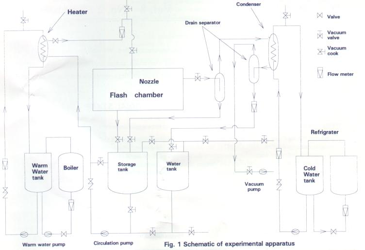
Figure 1 shows the schematic diagram of the experimental apparatus.
The experimental apparatus consists of a test loop, the warm water loop that suplies heat to water jets and the cold water loop that removes heat from the water jets.
The warm water loop consists of a plate type heat exchanger, a warm tank, a pump, and a flow meter.
The water, used as the working fluid, is pumped from a storage tank by the circulation pump, enters the plate type heat exchanger, its temperature is kept constant by the warm water that is pumped from the warm water tank and then injected downward through the circular tube nozzle into a flash chamber having two transparent sides for viewing and photographing. A portion of the water flashes off as vapor. Most of the vapor generated in the flash chamber condenses in the condenser and returns to the storage tank. The flash chamber is made of stainless steel. The dimension of the flash chmber are 0.85 m in width, 1.24 m in length and 1.32 m in height.
The temperature is measured by 26 thermistors. 17 of these are used to check steady state conditions and 9 are used to measure temperature in the liquid jet. Each 9 of the thermistors are fixed on the top surface of a piece that is movable vertically to measure the temperature of liquid jet formed by the colliding droplets. Uncertainties in the inlet liquid and vapor temperature are estimated to be ± 0.02¢XC, Uncertainties in the local jet length measured with a rule rod installed in the flash chamber are±0.5 mm. Uncertainties in measuring the flow rate of liquid using a rote-meter are ±2.0 percent. Uncertainties in measuring the pressure in the flash chamber using pressure transducers are ± 0.1 percent.
The nozzle used in the test is made of stainless steel with an internal diameter of 10, 15 and 20 ,, and a length of 81.3 mm.
The liqid is substantially demarcated by submitting it to more than 3 hours of preliminary flashing in the apparatus.
EXPERIMENTAL CONCLUSION
Experimental studies on the spray flash evaporation for a desalination plant and an OTEC plant using an intergrated hybrid cycle was carried out and the following results were obtained:
-
The spray flash evaporation can be to evaporated for the case less than that the inlet temperature of the superheated liquid
is 24¢XC. -
The flash evaporation is enhanced as the diameter of the nozzle is smaller, and the velocity of the nozzle and the superheat
of the nozzle exit are increased and the slope of an initial evaporation period become larger. -
The dimensionless temperature is estimated by empirical equation for I-H OTEC Cycle.

-
(4) the nonequilibrium temperature difference is estimated by empirical equation for I-H OTEC Cycle.

