Deprecated: mb_strpos(): Passing null to parameter #1 ($haystack) of type string is deprecated in /var/www/vhosts/argonautes.club/httpdocs/libraries/vendor/joomla/string/src/phputf8/mbstring/core.php on line 41
Deprecated: mb_strpos(): Passing null to parameter #1 ($haystack) of type string is deprecated in /var/www/vhosts/argonautes.club/httpdocs/libraries/vendor/joomla/string/src/phputf8/mbstring/core.php on line 41
News Special
The GreenOcean Project - Sustainable energy, food and water for the 21st century
The GreenOcean Project founder and editor of OTECnews
In modern energy terms OTEC is, as you probably know, a fairly old concept. The idea was first mentioned in 1881 by Jacques Arsene d'Arsonval and one of his students built an experimental open-cycle OTEC system at Matanzas Bay, Cuba, in 1930. However, when you talk to people today involved with (or interested in) renewable energy, hardly anyone knows anything about OTEC and its potential. That OTEC resides in obscurity is not a new insight. Several references to this have been made in recent IOA Newsletters, which was one of the inspirations for OTECnews and its parent organisation, The GreenOcean Project.
We believe that a more holistic view of the requirements of power production is gradually emerging in the general media and thereby the public awareness. The head of the European Union's Competition Commission, Mario Monti, has just confirmed that the UK Government's ¢G650 million (US$975 million) bail-out of nuclear power firm British Energy is unlawful. The Observer, a British Sunday newspaper, reported on 3 November 2002, that this bail out would keep British Energy afloat for two months, but equally could build enough onshore wind energy power generators to power 15 percent of the country. Scientific American's October 2002 cover story was about hydrogen-powered cars for the near future. No longer is global warming talked about as a hypothetical "possible future" in the media. Flood devastation in central Europe this summer put our impact on the environment firmly on the day-to-day agenda in most European governments. Our audience, the media - and in extension - the general public, is ready to listen.
OTECnews -The news source for Ocean Thermal Energy Conversion (OTEC)
OTECnews was started in October 2001 with the goal of regularly publishing information about the latest development around OTEC and related subjects, such as environmental impact, mariculture, ocean engineering, global climate change, energy policy, alternative energy and global fresh water supply. The intent is to report not only on OTEC development, but also on the context of the development of an OTEC power infrastructure. As a distinctive feature of OTEC energy systems, the end products include not only energy in the form of electricity, but potentially also fresh water and food. This means that to successfully implement OTEC power in the next decade, one needs to understand the commercial, environmental and energy-political environment in which OTEC power plants will be built. High awareness about OTEC among politicians, government administrators, media pundits and industry experts is a key goal to get OTEC power plants built. We believe that OTEC power generation has nowhere near the profile in the media that it needs to have: the OTECnews site is the first in a number of steps we are planning to take to help rectify that.
The GreenOcean Project
We felt that an inclusive approach would be the appropriate way forward to educate and raise awareness about OTEC and other synergistic technologies. Therefore we have organised ourselves around the concept of sustainable energy, food and water production linked to our oceans. So we started The GreenOcean Project, a non-profit organization, as the parent organisation for our efforts. The GreenOcean Project currently has three active projects: OTECnews, which is described above, the OTEC Library and a multi-part TV documentary series called "The GreenOcean"
OTEC Library
In our efforts to understand OTEC and its history we found that it was quite difficult as non-academics to get access to papers and other information about OTEC. There was no central resource and little information was available online. As part of our information gathering we decided to create an online OTEC information library - called the OTEC Library- to promote easier OTEC research for others as well as for ourselves. This project is very much in its infancy at the moment, but Phil Kopitske helped us enormously by giving us access to his research papers, collected for over a decade. As OTEC is a relatively obscure subject, we would encourage everyone who has access to papers, articles and books about OTEC (including what you yourself have written) to contact us so that we can either collect and make available these materials on our web site, or jointly work together on this project. The beginnings of the OTEC Library can be found at: http://www.OTECnews.org/oteclibrary.html
The GreenOcean -TV documentary series
To our knowledge there has been no TV documentary made about OTEC for the last ten years. There was a BBC documentary over decade ago, but there has been nothing about the recent exiting developments in the OTEC world. After talking to friends and colleagues in television and media it was clear that a TV documentary series would be viewed with considerable more favour among broadcasters than a single programme about an obscure subject. In spring this year we set out to make a multi-part TV documentary on new ways of utilising ocean resources for sustainable energy, food and fresh water production, with the minimum of impact on the environment. The pilot episode about the Seawater Greenhouse is soon to enter the editing phase of production and will be ready in early 2003. The Seawater Greenhouse uses cold sea water and sunlight to allow fruit and vegetables to be grown in otherwise arid regions, whilst functioning as a solar distillery to produce all the fresh water needed for irrigation. The next episode, which we hope to start working on during the spring of 2003, is planned to cover OTEC efforts and progress around the world.
To find out more about us and our efforts
please visit us at: http://www.OTECnews.org/
or email me at
- Détails
- Écrit par : Argonautes
- Catégorie : iOA News Letters
George Claude's Cuban OTEC experiment...
IOA News Letters Summary
... a lesson of tenacity for entrepeneurs
by Martin G. Brown, Michel GAUTHIER, Jean-Marc Meurville.
Introduction
At the dawn of the 21st century a proposal first postulated at the beginning of the 19th century lies virtually dormant, namely "Energie Thermique des Mers" or OTEC1 as it is normally referred to today. Although the concept has been known for over a hundred years and could be of major benefit to mankind, it has so far not been exploited to any significant extent.

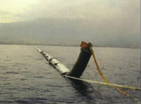
Fig. 1 Deployment of Claude's Cold water Pipe in Cuba in 1930
Given that many of the present day OTEC researchers have been working on the concept for many years it is easy to become discouraged by the lack of progress. It is here that the vision and tenacity of Georges Claude serves as an example to us all. This paper therefore illustrates some of the problems faced by Claude and shows how, in the main, he overcame them. It also points out that some of the problems experienced in the 1930's could be solved using up to date technology.

Fig. 2 ATwo2 Kilometers long pipe was installed in the Bay of Matanzas
to supply the On-shore plant with cold DOW (Deep Ocean Water)
It has often been found that new concepts are difficult to accept as they raise questions and doubts about established ideas. This applied to the proposals of Georges Claude and his fellow engineer Paul Boucherot when addressing in the 1920s the possibility to convert ocean thermal energy using sea water as the working fluid via the so-called OTEC Open Cycle.

Fig.3 Mechanical Engineering cover and article, from 1930
The main detractor's arguments related to the power needed for pumping deep sea water and extracting gas that would overcome the gross power of the plant, the heating of deep sea water during its ascending trip to the plant and also skepticism about the capacity for the piping to resist the harsh marine environment .Claude, after having demonstrated the thermodynamic validity of Open Cycle OTEC with his Ougree experiment2, decided to go one step ahead to demonstrate OTEC feasibility when using sea water in a tropical on shore Open Cycle plant. The site chosen was located on the island of Cuba in the Caribbean.
1.Ocean Thermal Energy Conversion. OTEC
2.In Spring 1928 Claude used the Meuse River's water outflow from a chemical factory cooling effluent at 33¢XC and the natural temperature
of the river at 12¢XC to run an Open Cycle experiment. He obtained an electric gross power of 59,4 KW. The total loss of power for pumping
and degassing was 11 kW with Cold and Warm water flows both set at 0.20 cubic meter per second.
The Cuban Epic
he Cuban installation was designed to run the 60 kW machinery previously used in Ougree with a cold water pipe 2 meters in diameter. A pipe not larger than 0.6 meter in diameter would have been large enough to feed the turbine, but the pipe diameter and the pumping equipment were intentionally oversized to minimize the warming up of the deep water during its ascent to the surface. Another reason being probably to better approach the difficulties to install and maintain at sea a pipe of a size close to that necessary to run small commercial plants of few Mega Watts.
Claude was a dynamic individual who did not believe in endless desk studies. Hence when he needed to find an appropriate site in Cuba he carried out the survey himself in 1927 using his own yacht the "Jamaica". This survey revealed a general topography feature around the island consisting of a submerged gentle slope from land to about 20 to 30 meters depth followed by a vertical cliff of 100 to 200 meters. This unexpected feature would not allow the pipe to lie all along its length on the bottom as originally planned. It would have to drop down "like an huge arch' to the depth of 700 meters, which was the maximum one could find in the bay. This imposed to find a site with a coastal current as small as possible to minimize the stress on the suspended portion of the pipe. The choice was to site the plant in the Bay of Matanzas, 10 km from the town of Matanzas and 100 km East of Havana, where currents were steadily under half a knot.
Building the OTEC Plant
The construction of the plant, the pit for cold water and the 50 meters long trench to bury and protect the landing part of the cold water pipe began early in 1929. During the same time in the customs house of Matanzas the cold water pipe was made out of 2 meters steel cylinders 2 millimeters thick "deeply corrugated" which had been transported from France. It was welded together in lengths of 22 meters with flange ends and rubber gaskets, and finally painted and insulated. Sufficient lengths were stored at the wharf of the Munson Line located 2 kilometers away, awaiting floating out and connecting together at sea to form a 2000 meters long cold water pipe. This last phase of the pipe construction had been scheduled during a few days period of calm weather during the fine season, but rough sea condition unexpected in that period of the year resulted in loss of some hundreds of metres of pipe. Today we have the advantage of improved weather forecasting that helps to minimize the risk involved in such an operation.
This accident, due to both rather hazardous site location and poor meteorological forecast, obliged Claude to modify his plan for the pipe installation. He decided to assemble the cold water pipe on a river, the Rio Canimar (because of the crocodiles living there) that runs into Matanzas Bay. The river was rather sinuous and meandering, but Claude knew the long pipe was flexible enough to adapt the windings of the river.
They first had to dredge a 250 meters wide sand bar that was partially obstructing the mouth of the river. Next they transported one by one the 22 meters pipe lengths with their attached floats across the bay far enough upstream the river and assembled them while maintaining the assembly anchored on concrete blocks sunk in the river. This was achieved by towing using steam powered tugs. At the end of August 1929 the pipe assembly was completed and ready to be towed out from the river down to the plant site in the bay 7 km away from the river's mouth. This was a one shot operation, since towing back the pipe in the river would be impossible because of the adverse currents. With a favourable several day weather forecast the signal was given to the tugboats to start pulling the pipe out of the river. Unfortunately the middle part of the pipe ran aground on an undredged portion of the sand bar at the river's mouth and its rear "folded into an accordion and suffered severely" However, the pipe was freed and refloated during the night thanks to the combination of the high tide and the efforts of the tugboats. Unfortunately it had been seriously damaged and the whole pipe sunk in 500 meters depth of water a few hours later on its way to the plant site. Unfortunately Claude did not have the advantage of modern maneuverable tugs with precise satellite based positioning systems.
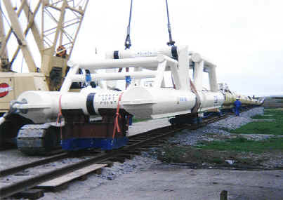
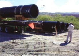
Fig. 4 Modern Day Deployment of an Oil and gas Pipeline Bundle
The budget allowed to Claude by his partners was gone and Claude decided to take charge, at his own expense, the construction and installation of a third pipe. This was an example of Claude's tenacity or stubbornness, which is perhaps one of the key characteristics of a great engineer. Under the suggestion of "Senior Vasquez", a Cuban engineer put at Claude's disposal by the Cuban Government, a new procedure was adopted. The bright idea was to assemble pipe portions on small wagons traveling on a railroad track laid perpendicular to the coastline behind the plant and to pull it to sea by winches and tugs. It is fascinating to note that this is the same methodology used today to launch oil and gas pipeline bundles (see Fig. 4). This is also the method that was used to launch the CWP used for the "OTEC-1" 1 MW size test ship deployed by the Americans in 1981 (see Fig. 5).
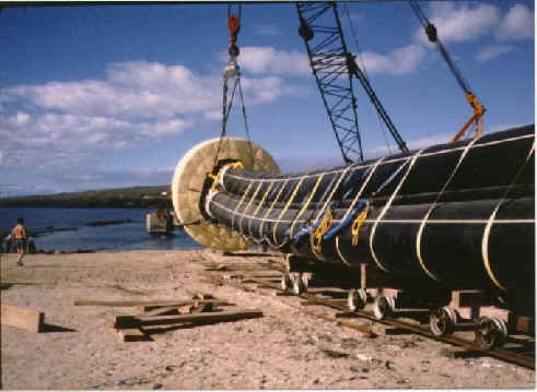
Fig. 5 Deployment of the OTEC- 1 CWP in 1981
The manufacturing of the third pipe began at the beginning of March 1930. It was 1.6 meters in diameter and made "entirely on the spot of Armco sheet 3 mm thick, rolled, welded, corrugated and insulated". To minimize the risk of installing in one run the whole 2000 meters long and 400 tones pipe assembly, the procedure was to install it in sections. The first CWP section (A) of 150 meters would run from the cold water pit dug on land down to a depth of 18 meters. Then a second length (C) of 1750 meters of pipe would be positioned to allow easy connection in shallow water to part (A) by hard hat divers thanks to a third portion of the CWP (B), the length of which had been adjusted to fit the gap between (A) and (C) see Fig 6. Interestingly today the cold water pit is known as Claude's pool and is a favourite swimming spot for local Matanzas Bay school children.

Fig. 6 Schematic Plan View of the Deployment of Claude's CWP
After an unsuccessful trial, part (A) was installed on June 8, 1930 and the trench filled up with concrete to avoid this landing part of the CWP from being damage by wave forces. Seventeen days later from the rail track close to the sea the pipe was pulled and positioned by no less than 12 tugboats in the direction of the landing trench. The (C) part was maintained in proper position by two "V" shaped cables moored onshore from each side of the pit. The final maneuver was to gently sink the CWP by deflating the floats starting from the shore end towards the sea. Unfortunately as reported by Claude "his written order was not respected" and the pipe was sunk the sea end first, overloading the mooring cables which "gave way and the tube went to joint the first" Sadly Claude did not have the benefit of walkie talkie radios and instead had to rely on megaphones for communications ! Thus if something started to go wrong during the operation it was difficult to pass on the instructions necessary to correct it.
Once again Claude decided not to give up even though his fortune was being depleted at an alarming rate. A third tube was constructed, pulled to sea on September 7th, 1930 and sunk at the right position to be connected to the intermediate section (B).
Operating the OTEC Machinery
A few days latter the cold water was pumped ashore at the rate of 4 cubic meters per hour and the temperature in the pit came down to 13 ¢XC. Claude "assumed" the temperature at the lower end of the tube was "probably" around 11 ¢XC, but he probably did not have the required instrumentation to confirm this. After adjusting the outflow to 1 cubic meter, i.e. to a velocity of 0.5 meter per second in the tube, the head loss measured in the pit was 3 meters. Some days latter a test of the boiling sea water under a vacuum showed that it was acting like fresh "pure water" without producing foam that, as some Claude's detractors had predicted, could have severely jeopardized the operation. Finally the small Ougree turbine was run with power slowly increasing up to 22 kW with equal inflows of 0.2 cubic meters per sec for warm water at 27 ¢XC and cold water at 13¢XC3. and outflows from boiler and condenser at 25 and 15 ¢XC. This allowed Claude to estimate a "mean 300 gross kW or 240 net kW for every cubic meter of cold water per second and a difference in temperature of 24 ¢XC" without accounting for the "numerous possibilities of improvement" His conviction strengthened by the success of the experiment led Claude to propose a 25 net MW OTEC plant in the "vicinity of Santiago de Cuba". He was considering this 25 MW plant as a necessary step forward to large commercial OTEC systems of "hundreds of thousands of kW" at price as low as $60 (1930)4 . We know today Claude failed to collect the funds necessary for building the Santiago plant. However, he continued to pursue his goal concentrating on a floating system with a vertical CWP, the same approach was used in Mini OTEC, the first system ever to produce net power from the ocean's thermal gradients in 1979.
Note. Most of the material for this article is extracted from the following references:
A."Power from the tropical seas", by Georges Claude. Mechanical Engineering Vol 52, December, 1930. N¢X 12 , in
English, pages 1039 -1044.
B.Histoire et politique en matiere d'energie thermique des mers, by Jean-Marc Meurville. These de DEA. CNAM,
septembre 1995, pages 36 a 42.
C.? Ma vie et mes inventions ?, G.Claude, Plon, 1957, in French, pages 135 a 145.
Footnote
Following an initial Scottish Trade Mission to Cuba in November 2000, Martin Brown is hoping to arrange an expedition to Matanzas Bay to explore what remains of Claude's experiments. The hope is to collect sufficient material to support a TV documentary on Claude's work and the potential of OTEC in general. Any fellow OTEC supporters who might be interested in joining such an expedition are encouraged to contact Martin. In addition, Martin is anxious to track down any drawings or photographs of the layout of Claude's experiments at Matanzas Bay.
3.Claude hypothesis for the deep water temperature fluctuation from the initial 11¢XC to 13 ¢XC was "curious fluctuations of Gulf Stream"
and leakage in the upper portion of the tube.
4.This is equivalent to 2000 French 1930 francs ( Reference A) i.e. very approximately 6000 Euros/ kW or today US 6/W.
- Détails
- Écrit par : Michel Gauthier
- Catégorie : iOA News Letters
About the IOA...
IOA News Letters Summary
... in general and the news letters in particular. An open letter from Michel Gauthier.
by Michel Gauthier, IOA Acting Chairman.
Dear friends and IOA Members,
I have received the news from our IOA secretariat that Taiwanese authorities would change from editing papers issues of the IOA Newsletter as they have been doing for the past 13 years, but the plan to maintain the publication in an e-mail format, and on the IOA Web site. This inspired me to set down the following thoughts.
This decision marked the end of one important feature of an old adventure launched 13 years ago thanks to the visionary interest of Dr. C.Y Li for promoting worldwide both OTEC development and Taiwan international influence. During that past period I know hundreds of people have enjoyed receiving these beautifully printed and interesting publications that linked the OTEC/DOWA world community. For those men like me that are born B.C, I mean Before Computer era, it was not only an intellectual pleasure to read the IOA Newsletter quarterly issues but also a physical one to touch its glazed paper and look at its colorful illustrations. It was also a publication I was proud to show (and recommend for subscription...) to new or potential "members" of the OTEC/DOWA community. Let me add this gave me many opportunities to tell people it was made possible because of Taiwanese generous funding.
There is a French proverb that says " Best things cannot last for ever " ! Well the best I can do with the old IOA Newsletters I have carefully stored at home is to have them nicely bound and saved for future generations of nostalgic "paper" books lovers.
But the present world does not leave much room to nostalgia. It stresses more on being Positive than Romantic. And surely, as the proponents of one of the most beneficial marine renewable energies, we should be looking ahead in every way -and that's what e-mail is about. Moreover, it gives us the opportunity to have more flexibility in the quarterly newsletter - full color photographs for example. And this suggests to me other thoughts which I briefly address to conclude this open letter.
Since our Taiwanese friends have announced they would maintain funding the IOA secretariat and the IOA Web site including an e-mail quarterly IOA Newsletter I strongly feel we do have to be grateful to them for keeping on and carrying the burden alone. I also believe we should think more about the future we envision for IOA and how our - still too small community - could be enlarged, strengthened and more involved in supporting IOA activities and helping the secretariat, both practically ( supplying articles to the secretariat being one way but probably not the only one to be considered ) and financially.
From many directions I received signals that Solar Energy is gradually imposing itself on public opinion as evidence that it is an indispensable, if not the only, resource enabling sustainable social & economic development for future generations. It would be dramatic if IOA, by lacking our support, does not benefit from the same ascending acknowledgement to increase its momentum and its international influence. New ideas and new blood are necessary to adapt IOA to future evolution.
My ultimate message in this last paper copy of the IOA Newsletter is to call for candidates to contribute and take responsibilities in IOA actions. Please send your ideas, comments and candidacy proposals to the secretariat.
Thank you in advance.
Tres cordialement
Michel Gauthier
- Détails
- Écrit par : Argonautes
- Catégorie : iOA News Letters
Itec-Iceberg Thermal Energy Conversion
By Georges MOUGN -W.P.I
ABSTRACT
Tabular iceberg transfer is now becoming feasible, thanks to new satellites data and means developed by the oil offshore industry.
Control of iceberg melting is performed by an OTEC open cycle plant but without cold water pipe, named ITEC.
Lower investment cost and a better efficiency allows a kwh cost of one third of the equivalent OTEC kwh.
Tabular icebergs from the Antarctic are potential sources of fresh water and power.
Transfer of these large bodies of ice, up to 300 million tons, contemplated twenty years ago, was then postponed due to the lack of information on the bathymetry and on transient currents in real time.
These informations are now available, brought by satellites like TOPEX POSEIDON !V JASON !V ERS II and soon ENVISAT.
Most obvious uses for melted iceberg water is to augment supplies for both urban and agricultural uses.
In fact should iceberg's delivery be established, entirely new areas may be in time developed at formerly inhospitable locations.
Fresh water from iceberg also appears as a major possibility in combating rising saline water tables as experienced in many areas.
In all instances iceberg's exploitation requires the conversion of ice into water.
Solar radiation !V 5 to 8 109 J m-2 yr-1 can only melt in one year 6 to 12 m of ice thickness (with albedo attenuation) and even less in foggy areas like the PERU and North CHILE shores.
A larger yield is needed, and melting should be controlled.
An iceberg of 1011 kg represents through the ice latent heat quite a large cooling power !V 3.35 x 10¹⁶ J.
One use of it would be its conversion to electrical energy through a process similar to the OTEC open cycle.
By analogy it has been named ITEC for Iceberg Thermal Energy Conversion.
ITEC process is a new concept which has to be valided by experiments of condensation directly on ice to optimize ice chips size and the compressor for the gas released by the ice.
ITEC should present some advantages in comparison with OTEC:
| Investment cost is reduced !V Cold Water Pipe and pump are avoided | |
| Cold water pump energy saved | |
| Efficiency is improved by greater temperatures' difference between warm and cold water | |
| Steam condensation taking place directly on a slurry of ice at 0¢FX. | |
| Fresh water produced by steam condensation is directly added to the flow from the condenser without heat exchanger. |
ITEC PLANT
The plant is similar to an open cycle OTEC plant but for the cold source.
A slurry of ice is produced in a centrally formed pond on top of the iceberg.
Iceberg top above sea level allows the condenser to be feeded by gravity. The plant being on a barge moored along the berg.
Ice volume is 10% air, to be released in the condenser, but the mass of ice to be introduced in it is 6.25% of the mass of cold sea water, warmed of 5¢FX, for the same cooling power.
Quantity of gas from the ice should be of the same order that the gas released from the sea water under 13 mbar.
If not, the compressor size has to be adjusted but the power requirement should not be increased significantly in regard of the energy gross output.
INVESTMENT
| No cold sea water pipe | |
| No cold water pump | |
| Simple condenser without heat exchanger |
These reduce the cost of the plant by 30 to 40%.
EFFICIENCY
| Energy used by the cold water pump is about 15% of the gross energy output. Without this pump ITEC ratio net to gross power is increased by 1.23 !V (0.80 instead of 0.65). | |
| Condensation is on ice at temperature near 0¢FX instead of 9¢FX in OTEC condenser. The temperatures' difference and Carnot efficiency are increased by 1.69 (ITEC difference of 22¢FX instead of OTEC 13¢FX) ; on the basis of cold water at 4¢FX warmed up of 5¢FX for condensation and warm water at 26¢FX cooled down of 4¢FX for evaporation. | |
| Together for the same quantity of evaporated warm water, net energy output is more than double (1.23 x 1.69). |
Kwh Unit Cost
-Lack of maintenance for cold water pipe and its pump
-Lack of cleaning of the sea water biofilm in the condenser since only soft water is in it.
| The ITEC plant investment is between 0.6 and 0.7 of the OTEC one. | |
| The energy output being double, the unit cost ot kwh ends up at one third of the OTEC one. | |
| Some savings on unit cost are also provided by: |
ITEC PLANT CAPACITY
A medium sized iceberg, whose transfer is economically feasible by the water value, represents a mass of ice of 108 metric tons.
For its utilization in 2 or 3 years 5,000 or 3,400 tons of ice have to be melted every hour.
If entirely melted through an ITEC plant its capacity would be 25 or 17 MW.
Added water production from sea water condensation would be 750 or 500 m3 per hour.
Icebergs are important resources of fresh water and power - ITEC being the process to combine both productions.
- Détails
- Écrit par : Argonautes
- Catégorie : iOA News Letters
Nelha Deploys 55-in deep seawater pipeline
by
Tom Daniel, Rick Hetzel
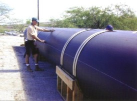
The Natural Energy Laboratory of Hawaii Authority, an agency of the State of Hawaii, has successfully completed deployment of its new 55-in diameter high density polyethylene (HDPE) deep seawater pipeline that extends to a depth of 3,000 feet, 9,700 feet offshore of NELHA's Hawaii Ocean Science and Technology (HOST) Park. The pipeline, designed for NELHA by Makai Ocean Engineering Inc. of Waimanalo, HI, will supply up to 27,000 gallons per minute of cold (39¢FXF), clean and nutrient rich deep seawater to commercial tenants in the 547-acre HOST Park area of NELHA, just South of Keahole Point, the western tip of Hawaii Island. This new pipeline will enable existing and new NELHA tenants to pursue research and commercial efforts toward utilization of deep ocean water, thus continuing NELHA's mission to expand and diversity Hawaii's economic base.
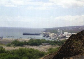
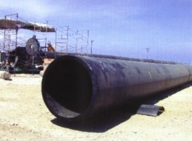
NELHA's prime contractor, Healy Tibbitts Builders, Inc. (HTBI), assembled the pipeline at Kawaihae Harbor, about 27 miles North of Keahole Point. The 60-ft long, 55-in OD pipe pieces from supplier KWH Pipe in California, arrived by barge in June and July 2001. The pieces were joined by heat fusion into 1,000-ft long sections, which were pressure tested and initially stored on shore. In September, concrete anchor weights were fastened to the pipe as the sections were pulled into the water. Blind flanges on the ends kept each section full of air so that the sections, with the anchors attached, floated on the surface of the harbor.
Following a one-week delay due to shipping problems resulting from the events of 11 September, HTBI began flanging together the pipe sections on Friday, October 5, 2001. The pipeline was towed out the harbor entrance as each successive section was connected, eventually stretching nearly two miles into the ocean. Several tugs and barges towed the assembled pipeline from Kawaihae Harbor to Keahole Point, arriving about dawn on Sunday, October 7th.
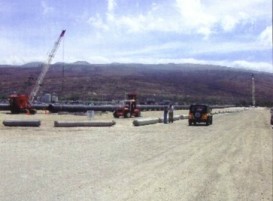
The pipeline was positioned along its intended offshore path. Four large bulldozers on shore held the nearshore end in position while the offshore end was pulled into the proper position by two tugboats. Cables fastened to a large pre-installed anchor established a required curve in the pipeline route. Pumps on a barge at the nearshore end began flooding the pipeline at 4,000 gallons per minute shortly before midnight on Sunday. Venting air through valves on the offshore blind flange controlled the pipeline air pressure. The tugs offshore provided a pull of more than 60 tons, as required to keep the pipe from buckling under the stresses of the sinking process. At shortly after midnight on October 8th, one of the two 4-1/4-in diameter nylon hawsers attaching the offshore end of the pipe to the pulling barge broke. Though no one was injured, the breaking of the line made it impossible to continue with the deployment. Large compressors on the barge pumped air back into the pipeline, forcing out the water and re-floating the nearshore pipeline and anchors.
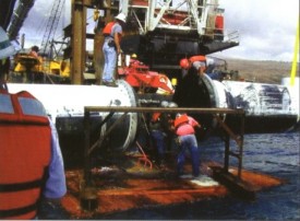
The pipeline remained in position on the surface until two new 270-ft long hawsers could be fabricated and flown in from Houston. The new hawsers arrived in Kona on Wednesday afternoon, October 10th and were installed for the final deployment, which went very smoothly on Thursday evening, October 11th. Once the pipeline was full of water, with the offshore end hanging about 90 ft below the offshore barge, divers were scheduled to remove the blind flange so that water could be pumped through the pipeline. Unfortunately, strong currents at that time made it impossible for divers to work, so the pipeline had to be lowered to the bottom with the blind flange still attached. The offshore pipeline intake reached its final position at 3,000 ft depth shortly after noon on October 12th.
Over the next three days, a remotely operated vehicle (ROV) removed all of the 22 nuts and all but three of the bolts around the blind flange, but the remaining bolts hung up on the polyethylene pipe. Efforts to "blow off" the 1-1/2 ton blind flange by pumping water through the pipeline were unsuccessful, so on the evening of October 15th, the ROV picked up a shackle lowered from another vessel and attached it to the flange. After the ROV retired to a safe distance, the flange was pulled free, leaving a successfully deployed pipeline on the bottom.
Subcontractor John E. Chance and Associates of Houston installed a series of acoustic transponders on the sea floor and Differential Global Positioning System (DGPS) transponders on all vessels to develop a navigation grid that provided highly accurate three-dimensional positioning throughout the deployment area. "DRONETM" displays, showing real-time locations of all vessels to within a few feet, were located in key positions on all major vessels and onshore.
Subcontractor, Underwater Technology Services, Inc. provided a Phoenix "Remora 6000" remotely operated vehicle (ROV) with 20,000-ft depth capability. In addition to a complete post-deployment survey showing the whole length of the deployed pipeline, this vessel provided, for the first time, real-time pictures of the weights touching down as the pipeline sank to the bottom. It was also used for removal of the 1.5-ton blind flange on the offshore intake at 3000-ft depth.
Now that the offshore deep seawater intake is successfully installed, the pipeline and a companion surface seawater intake structure are being connected to shore crossing tunnels installed several years ago. HTBI will then construct the onshore pump station, containing three 250-hp pumps each for the surface and deep seawater. A follow-on contract will install the onshore distribution pipes and booster pumps that are scheduled to deliver the seawater to HOST Park tenants beginning in July 2002.

The first barge arrives at Kawaihae Harbor, Unloading begins, 07:00, 10 June 2001.
9 June 2001.
Unloading pipe from flatbed at stroage area. Measuring Pipe diameter for quality assurance.

A completed 1000-ft. Pipe segment lies next A new 60-ft section is moved to the fusing machine.
to the fusion machine(left) which is fusing a
second segment .

The construction crew with NELHA A view of the assembly process from the mkai
representatives at the Pipline blessing opposite the fusion machine.
ceremony.

Assembly at Kawaihae: 5 October 2001. Removing the bind flanges in preparation for
joining the 1000-ft sections.


Joining two 1000-ft sections. Pipline leaving Kawaihae at Sunset, 6 Oct. 2001.

Intake just prior to intial deployment attempt, Pipline off Keahole Point, 11 Oct. 2001.
7 Oct. 2001.
- Détails
- Écrit par : Argonautes
- Catégorie : iOA News Letters
Energy Island
by Dominic Machaelis
The sea, the sea, ever renewed...Paul Valery
The Seas reveal many vast and diverse energy sources wind, waves, currents, tides, marine photosynthesis, geothermal and ocean thermal !Vwhich are too often only considered individually. Also, some renewable energy sources, often converted on land, can be more efficiently sea based. Wind energy is a typical example, where land features reduce its intensity and limit its locations. Land based wind farms have proven themselves to be visually unacceptable to many, while solar farms often occupy too much valuable land.
To best profit from the many renewable energy sources available at sea, the concept is to create an !¡±Energy Island!¡L which would take the form of a floating platform designed to harvest all usefully available energy sources, none acting in isolation, but all being brought together so that each acts to complement the other, adding its contribution to the whole.
A typical !¡±Energy Island!¡L may be of a hexagonal shape, measuring 500 meters along its shorter axis, with a surface area of 22 hectares. The hexagonal shape allows islands to be joined in clusters or linear modes according to planning intentions. Such an island is designed to provide a total of 250 MW, with 1/3 of the energy being contributed by ancillary sources and 2/3 by OTEC. The !¡±Energy Island!¡L is designed to utilize the following sources of energy.
Wave Energy: On the windward side, the island features linear wave energy converters, which can use one of the many different systems invented. Whether it is the oscillating water column, the !¡± lagoon!¡L , or another system, these converters play two roles in protecting the island from the heavy seas and then providing hydraulic energy to the platform to induce fluid flows or to generate electricity.
Wind Energy: Wind energy at sea is at its strongest, unaffected by land masses. The !¡±Energy Island!¡L has six large aerogenerators, three at a lower height (OMIT) to intercept the !¡± sea-hugging!¡L wind flow, while three are at greater heights to capture the upper wind flows. The hydraulic masts are able to adjust the heights of the aerogenerators to best harvest the wind potential from different directions.
 Sea Currents: Sea currents are powerful energy sources and can be intercepted by !¡± nets!¡L made up of linear arrays of cowled turbine units held up below the !¡± Energy Island!¡L by moored buoys between which they are stretched. Each unit has its own separate flotation buoy, the array taking up a slight catenary curve under pressure from the current. The main moored buoys have the capacity to be relocated below the island to accommodate shifts in the current direction. The array is positioned at a depth where it is little affected by wave energy, which is mostly expressed down to a depth equivalent to one sixth of its wavelength.
Solar Energy: Solar energy at sea level is at 900 Watts/sq.m, when the sun is directly overhead, and can be collected in many different ways. The hexagonal plan of the !¡±Energy Island!¡L suggests the possible use of a centrally located !¡±power tower!¡L furnace onto which are focussed heliostats or mirrors that can follow the sun, providing furnace temperatures around 800 ¢FJ which would allow relatively efficient electricity generation. Waste heat recovery of temperatures near the boiling point of water can be used and stored to assist thermal processes such as Ocean Thermal Energy Conversion (OTEC).
OTEC: OTEC in tropical waters can be the main source of electricity, with a combination of closed and open cycle systems for efficiency at different temperatures combined with desirable sea water distillation for a number of on- !¡± Island!¡L activities. All waste heat from the solar farm is used to enhance the surface water temperature, the surface water being channeled to the centrally located power plant along the six radial canals going to the outside apexes of the hexagon where floating dark membrane solar collectors optionally enhance the inlet temperatures. All warm and cold water pumping being carried out uses the ancillary energy sources deployed; these measures increase Carnet efficiencies and prevent OTEC from wasting the energy it is itself generating.
Apart from its electricity contribution, the !¡± Energy Island!¡L is designed also to produce hydrogen. Because of the fluctuation of renewable energy resources, an energy storage system is required. The !¡± Energy Island!¡L relies on a hydrolysis plant to produce stored hydrogen and oxygen, part of which can be used by fuel cell technology as necessary to balance the power output for both external and internal uses. Part of the fuel can, in some cases, be tankered or pipelined to other destinations, when the electricity produced is not totally used by cable links to nearby destinations.
The !¡±Energy Island!¡L will also produce a base for Controlled Environment Agriculture (CEA) and Mariculture. In tropical latitudes, greenhouses need to be protected from the sun, a role performed by the heliostats, and well ventilated or evaporatively cooled. The 22-hectare platform can therefore be used for CEA, using part of the distilled water from the open OTEC cycle for hydroponics. If the floor is trellised, light can reach the seawater below, where pens would contain various forms of marine life.
Harbours and Housing: On the leeward side of the island or islands, the !¡±Energy Island!¡L needs to provide housing for staff, social facilities, workshops and harbours.
The !¡±Energy Island!¡L uses many diverse renewable energy sources, bringing their converted powers together in the most efficient way to provide electricity for the grid, and, by hydrolysis, hydrogen fuel for transport to nearby or distant population centers, where it can be used efficiently by fuel cell technology. The !¡± Energy Island!¡L can become a major supplier of electricity and hydrogen fuel for a pollution free society, and liberate the world from the perils of nuclear power generation, and from its political, economic and polluting dependence on dwindling fossil fuels. The !¡±Energy Island!¡L therefore constitutes a new departure, demonstrated to be all the more necessary by the visible signs of pollution and global warming, and the frightening fact that world energy use is expanding exponentially, having doubled in the last thirty years. Action is needed to bring about change and turn the tide.
- Détails
- Écrit par : Argonautes
- Catégorie : iOA News Letters