Today, the main technical barrier to the development of OTEC systems is the successful design and fabrication of the cold water pipe (CWP). For floating OTEC platforms, the majority of CWP designs have considered a negatively buoyant pipe suspended from the platform by means of an articulated joint. Previous CWP designs and at-sea experience often showed the difficulty of designing an articulated joint able to accommodate the motion of the pipe and platform in all conceivable weather conditions. A fundamental problem associated with the CWP design was the tendency of one or more pipe natural frequencies to coincide with the wave excitation frequencies. A further problem with conventional designs was the effect of platform heave which might cause pipe damage. To overcome some of the problems that have been identified with previous CWP designs, Mr. Martin G. Brown, an installation engineer at Micoperi Offshore Ltd., London, U.K., recently proposed a new arrangement for a semi-submersible based OTEC system (Fig. 1). The CWP itself is positively buoyant and is attached by tension leg type moorings (1 in Fig. 1)to the seabed. At the top of the CWP, the pipe opens out into a funnel (2 in Fig. 1) into which dips a Pick-Up-Pipe. (The PUP corresponds to 3 in Fig. 1). The retractable PUP is attached to the platform. "Since the PUP and CWP are not connected, the motion of the platform is not directly transmitted to the CWP" Mr. Brown explained. This is significant because the number and the magnitude of the forces imposed on the CWP are reduced. A ring type semi-submersible is proposed as the ideal type of top structure since it has excellent seakeeping properties and is insensitive to incident wave direction. The proposed CWP arrangement could also be used with a conventional semi-submersible or with other types of hull form.
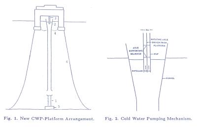
The flow rate used for the conventional system can be achieved in the PUP by faster pumping over a shorter length without frictional forces becoming too significant. This cold water transfer could be achieved by either applying suction at the top of the PUP or by using a platform driven impellor at the base of the PUP (see Fig.2).
Mooring ropes (4 in Fig.1) are provided between the funnel at the top of the CWP and the base of the platform. The mooring system for the platform (6 in Fig.1) is designed to keep lateral displacements to a minimum. The lowering of the CWP could be achieved either by pulling the pipe down using sea bed mounted winches (5 in Fig.1), or by reducing pipe buoyancy by controlled flooding of flotation tanks.
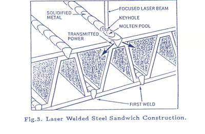
A sandwich structure that could be used for the fabrication of the CWP is illustrated in Fig. 3. In a similar manner to the effect of corrugation in cardboard, the inner web makes the sandwich same weight . Also, the open spaces between the inner and outer rings can be filled with syntactic foam or compressed air to generate the positive buoyancy required to support the weight of the pipe. The sandwich structure is made up from steel.
One of the areas of highest risk, regarding the danger of catastrophic loss is the CWP deployment. A possible way of reducing the risk associated with the installation process is to construct CWP section by section using a vertical deployment method.
Since the vertical assembly of a 1 km long pipe is unlikely to be completed quickly, the probability of bad weather occurring in the middle of the deployment process cannot be discounted . However, the sea-bed located winch facility provides a mechanism for protecting the partially installed CWP by lowering the pipe until weather conditions improve. The pipe lowering mechanism could alse be used for repair work and eventual decommissioning .
A major advantage of this new arrangement is the ease with which the CWP can be lowered below the sea surface without a complex disconnection procedure. Lowering the CWP reduces the magnitude of the forces imposed on the pipe , because wave and current loadings decay approximately exponentially with distance below the sea surface. Hence, significant reductions of the pipe loading can be achieved by lowering the pipe a relatively short distance below the sea surface. Since the pipe can be protected from environmental conditions by lowering, the need to design it to withstand very extreme storm loading is reduced. Thus, savings can be made on material and fabrication costs.
Mr .Brown emphasized that the dimensions of the PUP and funnel are designed to prevent any physical contact occurring . Hence, unlike a double gimbal or call and socket joint there will be no solid parts moving against each other and component wear will be minimized. Heave motions are also less problematic due to the proposed separation of the CWP and floater, resulting in the PUP simply moving in and out of the funnel. This removes the need for a heave compensator . Due to these factors and the simplicity of the new design, development and manufacturing costs are expected to be low.